The HPE Apollo 4200 Gen10 Plus is a 2U high-density storage server (legacy platform).
The HPE Apollo 4200 Gen10 Plus reached its End of Availability on November 1, 2025. End of Platform Support (EoPS) is November 1, 2030.
This page is reference material (drive bay layout and NIC port locations) for the HPE Apollo 4200 Gen10 Plus. For replacement procedures, see Replacing Hardware Components.
Drives
480TB and 240TB Nodes
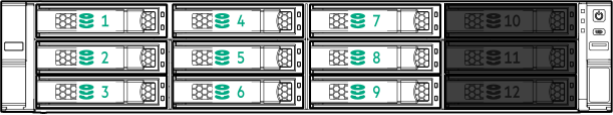
In 480TB and 240TB nodes, all drive bays are populated.
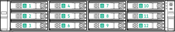
Front LFF Drive Row
The front LFF drive row, or cage 1, holds the first half of the drives in box 1, bays 1-12.
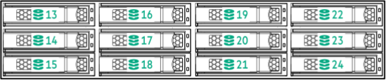
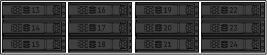
Internal LFF Drive Row
The internal LFF drive row, or cage 2, flips up behind the front drive row in the node. Cage 2 holds the second half of the drives in box 1, bays 13-24.
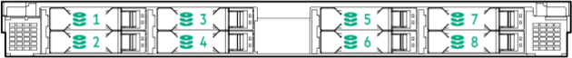
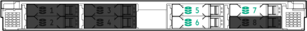
Internal SFF Drive Row
The internal SFF drive row flips up behind the internal LFF drive row. This row holds box 3, bays 1-8.
90TB and 36TB Nodes
In 90TB and 36TB nodes, some drive bays are empty.
In the following diagrams, empty drive bays appear in gray.
Front LFF Drive Row
Cage 1 holds the drives in box 1, bays 1-9. Bays 10-12 are empty.
Internal LFF Drive Row
Bays 13-24 in cage 2, box 1 are empty.
Internal SFF Drive Row
Bays 1-4 and 8 in box 3 are empty.
Boot Drive
The boot drive is located inside the node at the indicated location. The drive is mounted onto a PCI Express slot and connected to the motherboard with a SATA cable.
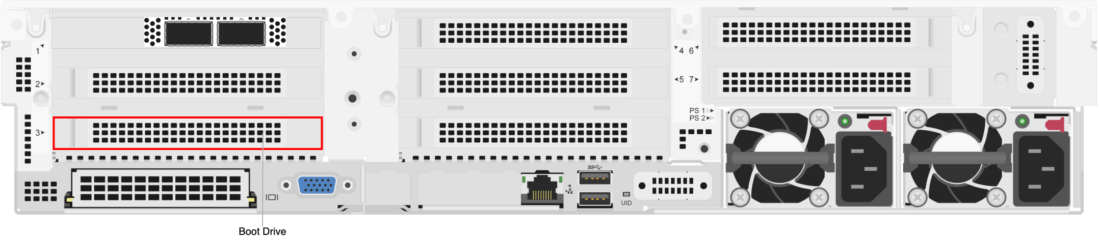
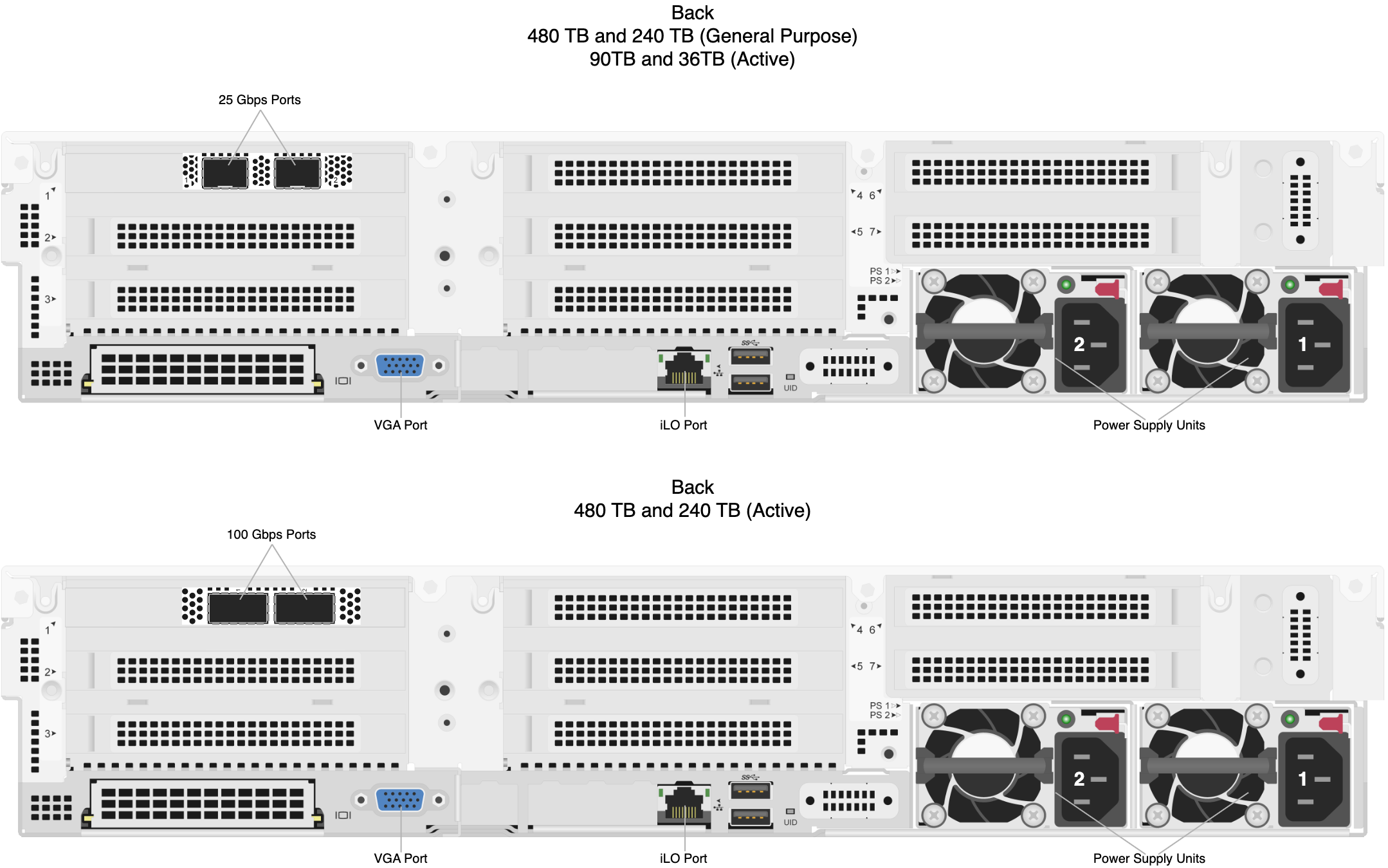
NIC Ports