This section explains how to configure cluster networking for platforms that use a split networking configuration.
In a split networking configuration, different NICs handle back-end (cluster) and front-end (client) traffic. You can connect the front-end and back-end NICs to the same switch or to different switches.
Identifying Ethernet Ports
To identify the
eth port, run the following command:for i in /sys/class/net/eth*; \
do echo $i; \
cat $i/device/uevent | \
grep -i pci_slot; \
donePrerequisites
Before you create your Qumulo cluster, if your client environment requires Jumbo Frames (9,000 MTU), configure your switch to support a higher MTU.
Your node requires the following resources:
- A network switch with the following specifications:
- Ethernet speed compatible with your NICs
- Fully non-blocking architecture
- IPv6 capability
- Compatible networking cables
- A sufficient number of ports for connecting all nodes to the same switch fabric
- One static IP for each node, for each defined VLAN
Recommended Configuration
We don’t recommend connecting to a single back-end NIC port because the node becomes unavailable if the single connection fails.
In a split networking configuration, we recommend connecting all four NIC ports on every node: Connect both front-end NIC ports to the front-end switch and both back-end NIC ports to the back-end switch.
We recommend the following configuration for your node:
- Your Qumulo front-end MTU configured to match your client environment
-
One set of redundant switches for the back-end network (9,000 MTU minimum)
Note
You can configure front-end and back-end traffic on the same switch. - One physical connection for each node, for each redundant switch
- One Link Aggregation Control Protocol (LACP) port-channel for each network (front-end and back-end) on each node, with the following configuration:
- Active mode
- Slow transmit
- Access port or trunk port with a native VLAN
- DNS servers
- A Network Time Protocol (NTP) server
- Firewall protocols or ports allowed for proactive monitoring
- Where
Nis the number of nodes,N-1floating IP addresses for each node, for each client-facing VLAN
Connecting to Redundant Switches
For redundancy, we recommend connecting your cluster to dual switches. If either switch becomes inoperative, the cluster is still accessible from the remaining switch.
- Front End
- Connect the two front-end NIC ports on your nodes to separate switches.
- The uplinks to the client network must equal the bandwidth from the cluster to the switch.
- The two ports form an LACP port channel by using a multi-chassis link aggregation group.
- Back End
- Connect the two back-end NIC ports on your nodes to separate switches.
- Use an appropriate inter-switch link or virtual port channel.
- Link Aggregation Control Protocol (LACP)
- For all connection speeds, the default behavior is that of an LACP with 1,500 MTU for the front-end and 9,000 MTU for the back-end interfaces.
Connecting to a Single Switch
You can connect your cluster to a single switch. If this switch becomes inoperative, the entire cluster becomes inaccessible.
- Front End
- Connect the two front-end NIC ports to a single switch.
- The uplinks to the client network must equal the bandwidth from the cluster to the switch.
- The two ports form an LACP port channel.
- Back End
- Connect the two back-end ports to a single switch.
- Link Aggregation Control Protocol (LACP)
- For all connection speeds, the default behavior is that of an LACP with 1,500 MTU for the front-end and 9,000 MTU for the back-end interfaces.
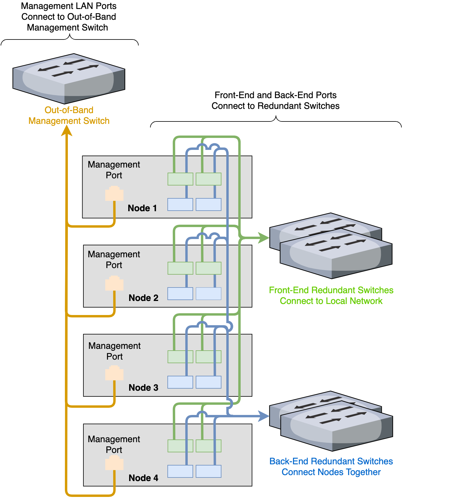
Four-Node Cluster Architecture Diagram
The following is the recommended configuration for a four-node cluster connected to an out-of-band management switch and redundant switches.