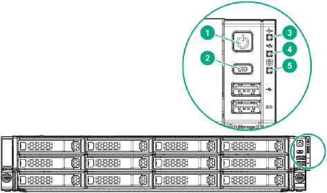
This section explains the LEDs on HPE Apollo 4200 Gen10 nodes, including front panel LEDs and buttons, power fault LEDs, and rear panel LEDs. You can use these LEDs to diagnose hardware health issues.
Front Panel LEDs and Buttons
To locate the front panel LEDs, use the following diagram.

-
Power On or Standby Button and System Power LED
- 🟢 Solid Green: System on
- 🟢 Flashing Green: (1 flash each second) Performing power-on sequence
- 🟠 Solid Amber: System in standby
- Off: No power present
-
UID Button and LED
- 🔵 Solid Blue: Activated
-
🔵 Flashing Blue:
- 1 flash each second: Remote management or firmware upgrade in progress
- 4 flashes each second: iLO manual reboot sequence initiated
- 8 flashes each second: iLO manual reboot sequence in progress
- Off: Deactivated
-
Health LED
- 🟢 Solid Green: Normal
- 🟢 Flashing Green: (1 flash each second) iLO is rebooting
- 🟠 Flashing Amber: System degraded
- 🔴 Flashing Red: (1 flash each second) System critical
Note
If the Health LED indicates a degraded or critical state, review the system integrated management log (IML) or use iLO to review the system health status. -
NIC Status LED
- 🟢 Solid Green: Link to network
- 🟢 Flashing Green: (1 flash each second) Network active
- Off: No network activity
-
Front Drive Health or Thermal LED
- 🟢 Solid Green: Drives which the SAS expander supports are functional. This applies to all front drives and the rear drives connected to the front drive cage 2 backplane.
- 🟠 Solid Amber: Failure or predictive failure of one or more drives that the SAS expander supports. This applies to all front drives and to the rear drives connected to the front drive cage 2 backplane.
-
🟠 Flashing Amber: (1 flash each second) The temperature sensor in one or more front drives is about to reach the thermal threshold. You must immediately slide the front drive cages back into the chassis and keep them there until the LED turns green.
Note
This LED behavior depends on the iLO 08-HD Max sensor reading. - Off: No power present
If the (5) Front Drive Health or Thermal LED, or the (1) Power On or Standby Button and System Power LED are off, one of the following conditions is possible:
- Facility power not present
- Power cord detached
- No power supplies installed
- Power supply failure
- Front I/O cable disconnected
Power Fault LEDs
If the (1) Power On or Standby Button and System Power LED, (2) UID Button and LED, (3) Health LED, and (4) NIC Status LED flash simultaneously, a power fault has occurred. The following table lists the LED behavior corresponding to affected subsystems.
| Number of LED Flashes | Affected Subsystem |
|---|---|
| 1 | System board |
| 2 | Processor |
| 3 | Memory |
| 4 | Riser board PCIe slots |
| 5 | FlexibleLOM |
| 6 | Removable HPE Flexible Smart Array controller or Smart SAS HBA controller |
| 7 | System board PCIe slots |
| 8 | Power backplane or storage backplane |
| 9 | Power supply |
Rear Panel LEDs
To locate the rear panel LEDs, use the following diagram.

-
Dedicated iLO Port 1 Link LED
- 🟢 Green: Network link
- Off: No network link
-
Dedicated iLO Port 1 Activity LED
- 🟢 Solid Green: Link to network
- 🟢 Flashing Green: Network active
- Off: No network activity
-
UID LED
- 🔵 Solid Blue: Activated
-
🔵 Flashing Blue:
- 1 flash each second: Remote management or firmware upgrade in progress
- 4 flashes each second: iLO manual reboot sequence initiated
- 8 flashes each second: iLO manual reboot sequence in progress
- Off: Deactivated
-
Dedicated iLO Port 2 Link LED
- 🟢 Green: Network link
- Off: No network link
-
Dedicated iLO Port 2 Activity LED
- 🟢 Solid Green: Link to network
- 🟢 Flashing Green: Network active
- Off: No network activity
-
NIC Port 1 Link LED
- 🟢 Green: Network link
- Off: No network link
-
NIC Port 1 Activity LED
- 🟢 Solid Green: Link to network
- 🟢 Flashing Green: Network active
- Off: No network activity
-
NIC Port 2 Link LED
- 🟢 Green: Network link
- Off: No network link
-
NIC Port 2 Activity LED
- 🟢 Solid Green: Link to network
- 🟢 Flashing Green: Network active
- Off: No network activity
-
Power Supply LED
- 🟢 Solid Green: Normal
-
Off: One or more of the following conditions exist:
- Power unavailable
- Power supply failed
- Power supply in standby mode
- Power supply error
