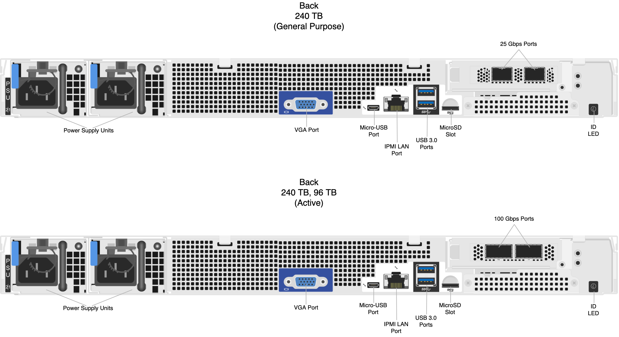
This section explains how to wire the out-of-band management (IPMI) port, 25 Gbps or 100 Gbps ports, and power on Quiver 1UH Gen2 nodes.
This platform uses a unified networking configuration in which the same NIC handles back-end and front-end traffic. In this configuration, each networking port provides communication with clients and between nodes. You can connect the NIC’s ports to the same switch or to different switches.

Step 1: Connecting the Out-of-Band Management (IPMI) Port
The dedicated out-of-band management port allows functionality such as remote display, control, and power. The port uses the Intelligent Platform Management Interface (IPMI) protocol.
The IPMI port is located on the back of your node.
For more information, see Default IPMI Usernames and Passwords 🔒 on Qumulo Care.
The IPMI username and password are unrelated to your Qumulo administrative credentials.
To configure the IPMI port, you must use the BMC UI. For more information, see the BMC section in the Quiver 1U Hybrid Gen2 Service Guide (p.107) 🔒.
To Configure the IPMI Port by Using ipmitool
Alternatively, you can configure the IPMI port by using ipmitool.
In the following examples, the lan set 1 command specifies LAN channel 1.
-
To change the configuration from DHCP to static IP assignment, use the
ipsrcsubcommand. For example:ipmitool lan set 1 ipsrc static -
To set the IP address, use the
ipaddrsubcommand. For example:ipmitool lan set 1 ipaddr 203.0.113.0 -
To set the subnet mask, use the
netmasksubcommand. For example:ipmitool lan set 1 netmask 255.0.0.1 -
To set the default gateway, use the
defgwsubcommand. For example:ipmitool lan set 1 defgw ipaddr 192.168.0.1 -
To enable Address Resolution Protocol (ARP), which Qumulo Core often requires for
pingto function properly, use thearpsubcommand. For example:ipmitool lan set 1 arp respond on -
To reset the BMC to allow the new configuration to take effect, run the
ipmitool mc reset coldcommand.
Step 2: Connecting the 25 Gbps or 100 Gbps Ports
After you connect the iRMC port, connect your 25 Gbps or 100 Gbps ports (compatible with QSFP28 and QSFP56). There are two 25 Gbps or 100 Gbps ports on the back of your node. This platform uses a unified networking configuration in which the same NIC handles back-end and front-end traffic. In this configuration, each networking port provides communication with clients and between nodes. You can connect the NIC’s ports to the same switch or to different switches.
To identify the
eth port, run the following command:for i in /sys/class/net/eth*; \
do echo $i; \
cat $i/device/uevent | \
grep -i pci_slot; \
doneStep 3: Connecting the Power
After you connect your 25 Gbps or 100 Gbps ports, connect power to the node. There are two power sockets on the back of your node. To maximize redundancy, connect each PSU to a separate power supply or power distribution unit (PDU).
